2D-Truss Analysis
While calulations based on the Method of Joints can only solve statically determinate problems,
the FEM based analysis of this page calculates support forces, truss forces and node displacements for 2D-truss structures that can also be statically indeterminate.
Steps to set up a new model:
- define the node points of the structure by their 2 coordinates (or double click in the pane)
- define each truss element by its 2 nodes (or drag the mouse bewteen 2 nodes) and its material number
- define the material data (cross-section A and Young's modulus E)
- define the loads
- define which node is supported in which direction
If all bars have the same cross-section A and the same Young's modulus E and you are not interested in displacements, you can simply enter 1 for A and E.
A and E have no influence on the bar forces in this situation.
When visualizing bar forces, the colors are different:
Trusses under compression in red, trusses under tension in blue and zero force members in white.
When entering data, there are no units. The user is responsible for providing data regarding consistent units
e.g.
point coordinates in m, loads in N, cross sections in m² and the modulus of elasticity in N/m²,
displacements then will be in m, bar forces in N, normal stress in N/m².
or
point coordinates in mm, loads in N, cross sections in mm² and the modulus of elasticity in N/mm²,
displacements then will be in mm, bar forces in N, normal stress in N/mm².
or
point coordinates in in, loads in lbf, cross sections in in² and the modulus of elasticity in psi,
displacements then will be in in, bar forces in lbf, normal stress in psi.
Additionally to the table of results the bars may be clicked to display the according force, the nodes may be clicked to show the according displacement.
Zero Force Members
Zero force members are members in a truss that transmit no force under a specific load on the truss.
For the purpose of simplifying the analysis of the truss, zero force members can be removed.
Situations involving zero force members are:
a) A truss corner with only two members and no additional force application. Both members are then zero force members.
b) A truss joint with three members, two of which are aligned in the same direction, and no additional force application. The third member then is a zero force member.
c) A truss corner with only two members and a force application in the direction of one member. The other member is a zero force member.
The identification and removal of zero force members can be repeated, because new potential zero force members may emerge after the removal of existing ones.
Example:
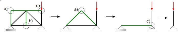
In the example shown, multiple zero force members can be identified and removed.
Ultimately, only one loaded member remains, which transfers the load into the ground. The left bearing is therefore unloaded.
Exploiting Symmetry
A symmetrical loading situation exists when, with respect to an axis of symmetry,
the geometry, material properties, load and support are symmetrical.
In this case, it is sufficient to model only one half of the truss, because forces and stresses are then also symmetrical.
The following applies to displacements:
Displacements parallel to the axis of symmetry are symmetrical with respect to the axis of symmetry.
Displacements perpendicular to the axis of symmetry are symmetrical in magnitude with respect to the axis of symmetry but have opposite signs.
To exploit the symmetry, proceed as follows:
The truss is split along the axis of symmetry.
Hinged nodes that lie on the axis of symmetry must be supported in such a way that a displacement perpendicular to the axis of symmetry is prevented.
For members that lie on the axis of symmetry If the cross-section lies on the axis of symmetry, it must be halved.
Loads acting on the axis of symmetry must be halved.
Bars whose end nodes lie on both sides of the axis of symmetry are halved and fitted with a support on the axis of symmetry that prevents displacement perpendicular to the axis of symmetry.
In the latter case, rotation of the bar should also be prevented by a support on the axis of symmetry. However, since rotation is not a degree of freedom for truss bars, this requirement is not possible.
This then results in the additional node that bisects the bar not being displaced under load (a minor flaw).
However, this has no effect on forces and displacements.
3D-Truss Analysis
Three-dimensional trusses can be examined here 3D-Truss Analysis.
more JavaScript applications